
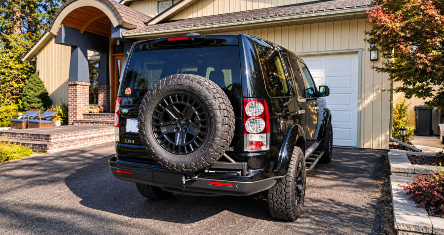
When looking for a spare wheel carrier, I couldn’t find much information about the Manx4. So I’m posting my experience installing it for anyone who is researching options for themselves.
Overall, I give it a 8.5/10. There’s a few minor things that I would design differently, but very impressed with the final product. And it suits the Disco.
Why add a rear swing-arm wheel carrier?
The LR4 (and LR3) is an incredibly well thought out SUV. I recently heard Land Rover compared with Rolex. They’re designed around practical function, but somehow grab the heart too. And when you drive one, you get it. But, Land Rovers are not perfect, nor are they claiming to be.
What Land Rover does have are decades of experience designing off-road vehicles, and I suspect the LR3/4 was a concept for the team. An opportunity. To combine all that experience into one package. And they nailed it with the practicality/utility of the design.
But, in my opinion, it has one flaw.
The stock tire carrier is stored below the rear of the truck. It’s possible to stuff a 32″ tire by deflating it and squeezing it in. But the thought of getting stuck in the dirt or mud with a flat and having to wrestle the spare tire out from under the vehicle, isn’t that exciting.
There are other challenges too. A full size spare wheel tucked under the vehicle gets in the way of an extended hitch. Something I discovered when borrowing a friend’s one.
The solution is a swing-away spare tire carrier. But I had concerns.
Would it be annoying unlatching a spare wheel to open the rear hatch?
Would it put unnecessary weight on the rear?
Would it change the driving dynamics of the vehicle?
I occasionally use my Land Rover to pick up lumber at the hardware store. I love that I can pop the hatch and run the boards out the back. The utility of the rear-hatch is a huge reason I chose the LR4. Would the spare tire carrier get in the way?
Some of these I will answer in a long term review. But I decided, the benefits gained from carrying the spare wheel on the back was worth it. So I went with the install, and I’m glad I did.
How to install the Manx4 swing away wheel carrier.
While it didn’t come with instructions, the install is relatively straightforward.
Step 1: Layout all the hardware.
The first thing I did was organize the hardware and then figure out what bolt/nut/washer went together.
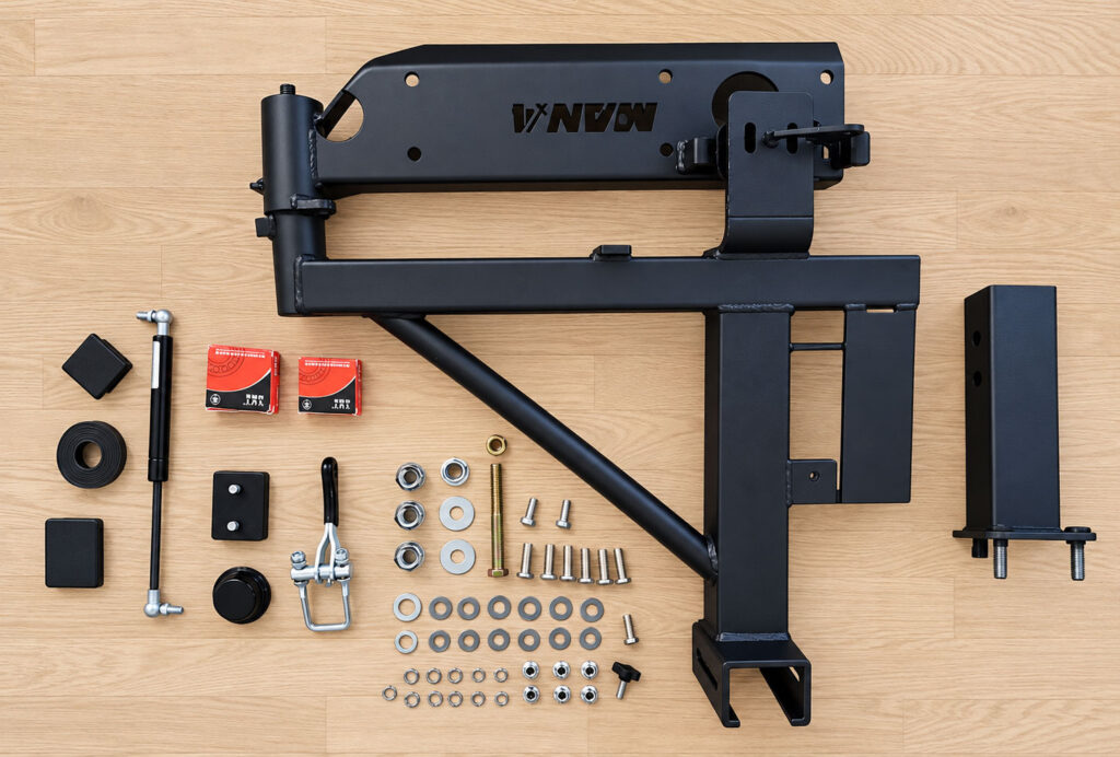
Having everything organize makes the next steps much easier.
Step 2. Remove both rear tail lights.
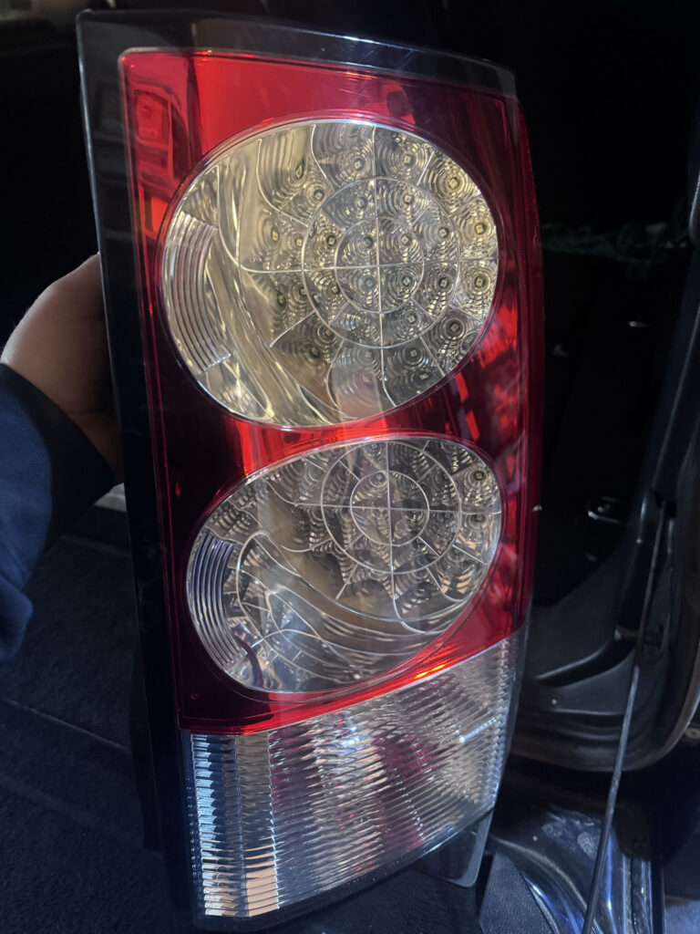
There are two Phillips (star) screws that are visible when you open the rear hatch. There are also two clips that hold it in. I found the easiest is to grab the taillight by the bottom outer corner, then pull it up and out. The clips release. And then disconnect each connector. There’s a small clip that you press in. Then you can pull the connector apart.
Step 3. Remove the rear side trim arches.
There’s a screw underneath and 3 push tabs. Remove those, then pop off the trims by pulling them out towards you, away from the vehicle.
Step 4: Remove the rear bumper.
There’s 4 screws directly under the rear of the bumper. And 2 screws (one under each side) that secures the rear of the bumper in place. Remove those.
Then there are 4 pop tabs on the top back of the bumper. You can see them by slanting the rear door and lifting the flap that rests against it.
There’s also 2 more pop tabs, one at each side of the rear of the bumper.
Step 5: Clean the rear steel bumper
With the plastic bumper removed, you can see the steel bumper. Mine was dirty and had minor surface rust. The first thing I did was to clean it out.
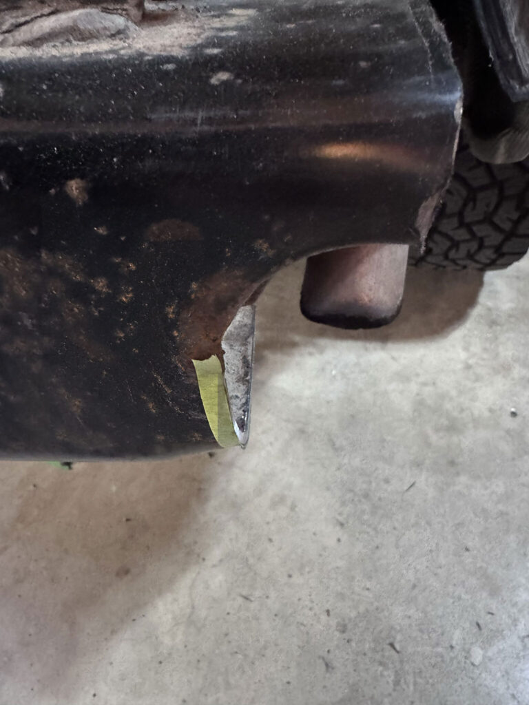
Step 6: Mark and cut the right side of the bumper.
The swing arm is held in place by a strong pivot bumper extension with a cylindrical part that bolts onto the existing bumper. You need to remove the end of the bumper to fit the cylinder that holds the pivot arm.
Then mark the area you want to remove.
For reference, I found cutting directly down where the circle is on the metal bumper. And on the top half, I cut it about the mid point of the circle on an angle then right across. It worked out perfectly. See the finished cut below.
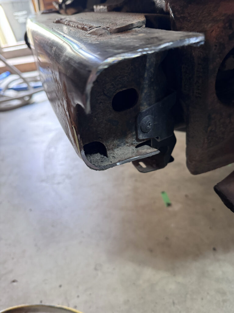
Step 7: Drill the holes in the bumper.
Install the bumper extension into position. This makes it easy to mark where you need to drill the holes.
My bumper extension took a mix of persuasion (wood block and steel mallet) to get in position. (Optional: I also ground down the welds on both the bumper and the Manx4 bumper extension. This made the install much easier.)
Line the bumper extension up with the large round holes on the bumper.
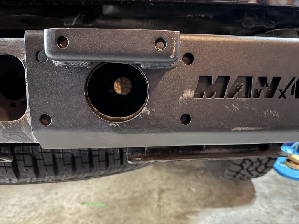
I drilled starter holes to centre the drill bit. A centre punch will do. Then completed them with the larger drill bit.
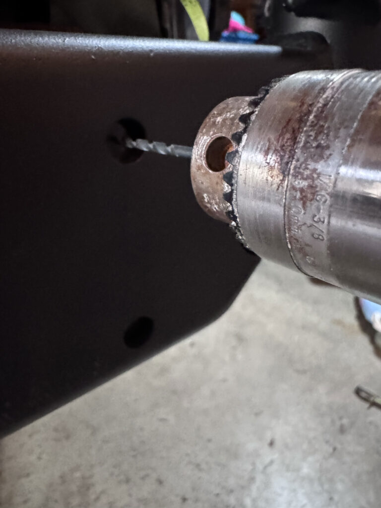
Step 7: (Optional)
After I had made the cuts and drilled the holes, then I dealt with the surface rust. (A steel brush, rust converter, and rust primer, followed by a top coat dealt with that. That’s for another post).
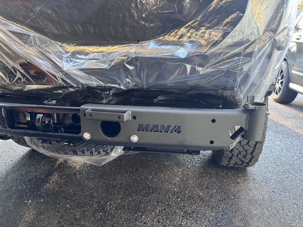
Step 8: Bolt the bumper extension into position.
The kit comes with nuts on the end of metal rods for positioning them inside the rear bumper. Very convenient, but way too long for all by the last two. So I cut them down to the distances needed. Gave it a clean look. And will reduce rattling.
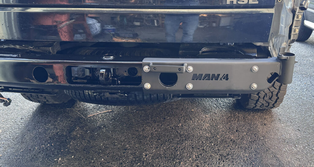
Step 9: Remove styrofoam in the bumper for the pivot point and the latch point.
Cut this out carefully as there are wires running behind the styrofoam for the parking sensors.
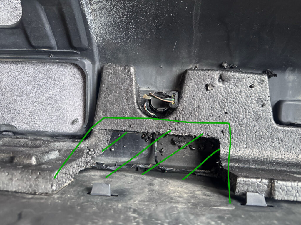
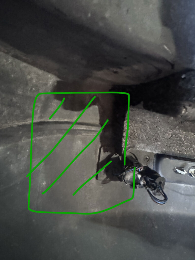
I then taped the middle wire from the sensor out of the way (see the wire in the middle of the green cutout area) so it wouldn’t get pinched between the bumper and the metal bracket.
Step 10: Cut out the hole for the pivot joint.
I measured roughly 5 times for this cut. I’m not kidding. It’s visible and it’s the one thing I didn’t want to get wrong.
I test fitted the bumper into position. Then climbed under the vehicle and marked the inside circle of the pivot joint with a permanent marker.
I used this as my baseline. I removed and test fitted the bumper numerous times in this process. Each time trying to get it as close as I could to where it would sit once installed. This was key to getting the location correct. I got it very nearly perfect.
I also used the template as a helpful guide, not for positioning, but to line up where to mark my holes from my reference marks, but I made the hole smaller. I used a 2 1/4″ drill bit. It was the perfect size. Then drilled a 1/2″ hole for the bold, and cut out the area for the stop carefully as I could. You don’t need to cut out a big whole. I’ll show you what I did. The end result was surprisingly tidy.
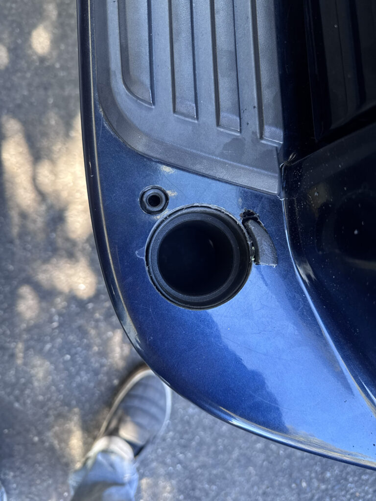
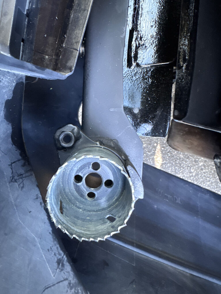
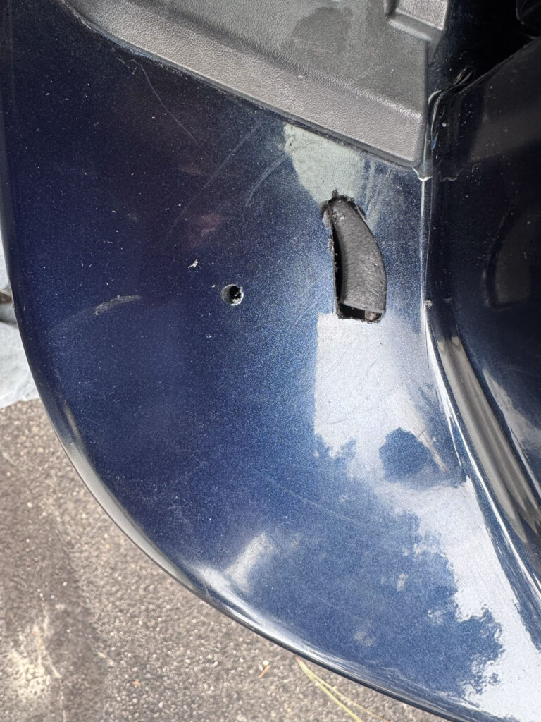
I placed the hole cutting bit to find the correct size. 2 1/4″ was perfect. The stop I did by hand, and it was my first cut. I used it as a reference point. So it was the least accurate as I had to make some adjustments as I went. But I used rubber to give it a finished look, which I’ll share below.
Step 10.5: drill out the holes for the latch bracket too.
Step 11: Install the bearings
I don’t have a hydraulic press. The bearing didn’t want to fit. So my method consisted of placing the bearing in a freezer for 30 minutes and heating the metal cylinder with a heat gun until it was very hot. Then I dropped the bearing into place and hammered it down with the round part of a ball joint. It worked.
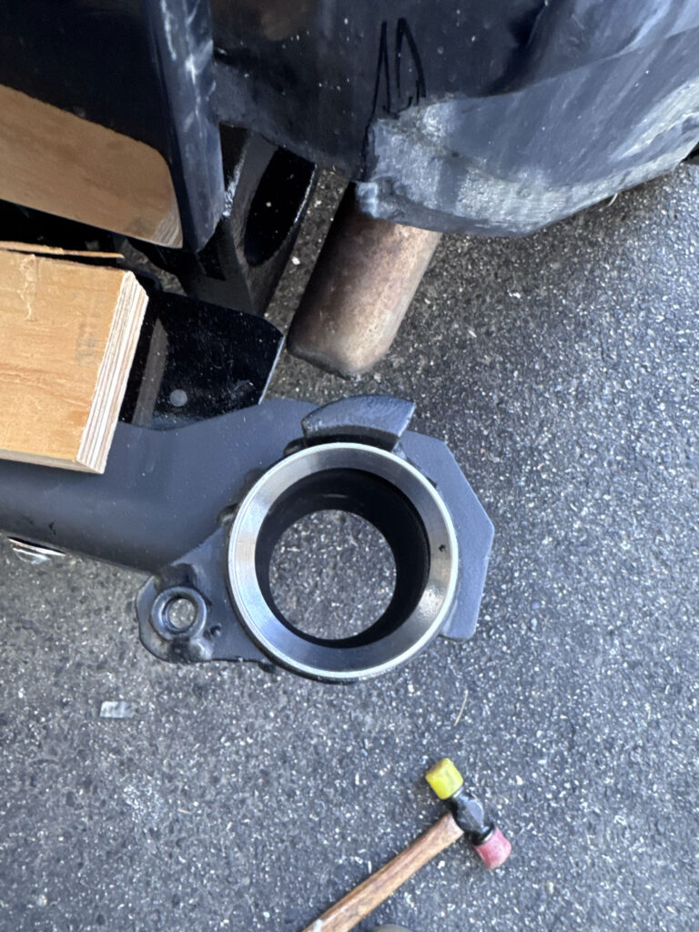
This photo was taken before I installed the top bearing.
The bottom bearing went in much easier.
The bearings are designed to squeeze together with the bolt. So the bezelled edges are facing outwards (opposite of each other). Once in place, the top sealed bearing drops into position. The bottom bearing you have to hold in place (or it will fall out), while you put the washer and 24mm nut in place when you install the swivel arm.
I test fit everything, and loosely bolted the swing away carrier in place. This ensured the bearings had seated to the right depth. Then I removed the bolt and the swing away carrier to reinstall the bumper.
Step 12: Re-install the bumper
Install the bumper in reverse of how you removed it.
Step 13: Install both taillights.
Plug the connectors back in place. I added dielectric grease, probably overkill.
Reinstall them in the reverse of how you removed them.
Step 14: Install the rear wheel arch fender flare trims.
Some of the fender flare retaining clips broke when removing the arch trims. So I bought a set from Amazon. They arrived the next day. After replacing them, I reinstalled the trim.
Step 15: Install the swing away tire carrier.
I didn’t take photos of this step. But it was fairly straightforward with the assistance of my wife who held the carrier arm in place.
First, drop the pivot spindle in through the top bearing.
Then climb underneath.
I had just enough room to use my hand to place the lower bearing into position, then while holding it there,so it doesn’t fall out, place the washer, and then install the 24mm bolt.
I used a 24mm wrench to tighten the bottom bolt. My wife held the tire carrier to stop it from swinging while I tighten in. I like this design, because it’s only one bolt to remove it.
Step 17. Install the bracket.
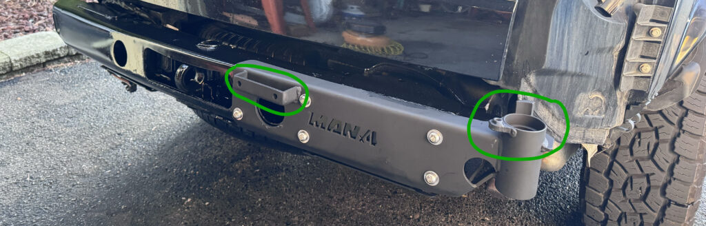
The bracket bolts directly onto the rear bumper. This is what the swing arm latches to.
Instead of cutting a hole in the bumper, I installed the bracket over top of the bumper. I added rubber (that I had in my garage) behind the top of the bracket to ensure the bracket sat level to the face of the mating swing arm latch. And, in my opinion, the finished result looks OEM.

I had pre-drilled pilot holes into the plastic bumper for the bracket with it removed. They were a few millimetres off. I re-drilled the pilot holes, then fitted the screws.
Then loosely install the rubber stopper to the swing arm.
Step 18. Install the swing arm latch.
I added washers to the inside of the latch, then tightened it down. Worked well.
With the swing arm latched, I then adjusted the nuts until the latch itself was tight and square to the lock.
Finally, I then tighten the rubber stopper in its final position.
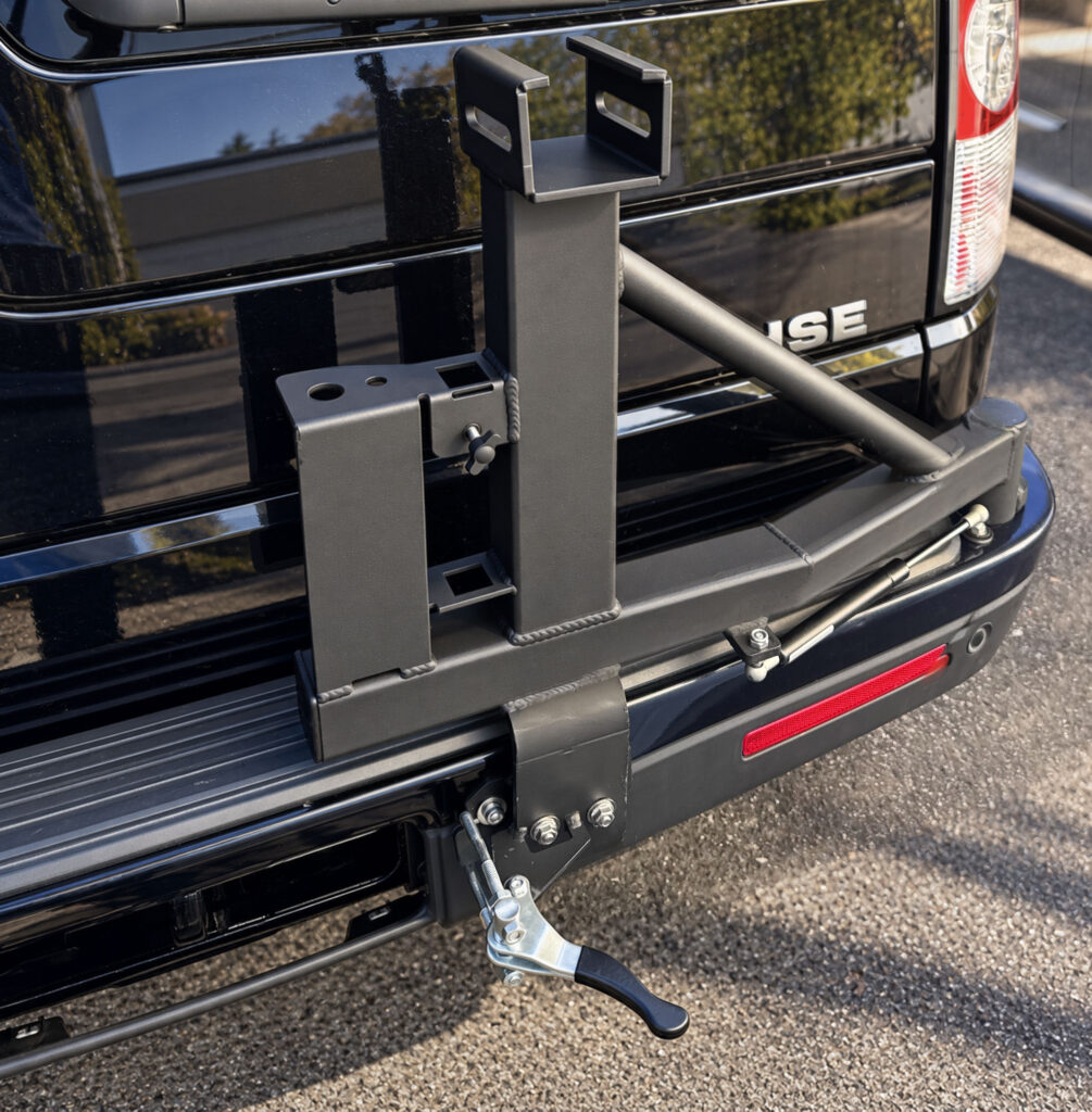
Step 19: Install the extension that the wheel bolts to.
A single bolt is used to fasten it in placer. I installed the bolt with the nut and washers. Then I tightened it in a few spots to ensure the metal bracket closed evenly on all sides when tightened the final time.
Step 20: Install your spare wheel.
The spare wheel carrier comes with 3 lug nuts. Which is great. They’re for the OEM Land Rover wheels. But they didn’t fit my aftermarket Black Rhino Alston wheels. So I had to get a set that did.
The spare wheel uses M12x2.25 threaded nuts. So unfortunately, your Land Rover nuts won’t fit. Not that big of deal at the end of the day. I ordered some from Amazon.
And presto, you have a very solid, well-built, and factory looking spare tire carrier.


Here’s what I like about the design of the Manx4 carrier.
It’s well made, strong and can easily carry the weight of the wheel.
The latch is solid. There’s a rubber block that sits between the swing arm and the bumper lock, holding the arm firmly in place when latched.
The swing arm and the pivot joint is one piece. Making it easier to install/remove the bumper. Also the swing arm is fully sealed.
The swing arm pivots on two bearings. When installed, the top bearing is creates a sealed surface. It’s a good design.
It’s relatively easy to remove the swing arm. There’s a single 24mm bolt that cinches the swing arm in place. When you undo it, you simply pull the swing arm out.
